Timing Belt Pulley - Installation
Special care has to be taken with the installation of timing belt pulleys. Being aware of the problems associated with a poor installation job will save you time and money. Misalignment is often one of the most common causes of drive performance problems. Misaligned drives can show symptoms such as:
- high timing belt tracking forces
- uneven timing belt tooth wear
- excessive timing belt edge wear
- high noise levels
- uneven load distribution
- timing belt tensile cord failure
The two main types of drive misalignment are ANGULAR and PARALLEL as illustrated in the below pictures.
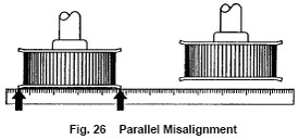
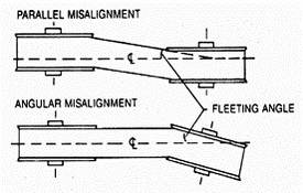
Parallel Misalignment
Parallel misalignment is where the driver and driven shafts are parallel but the driver and driven timing belt pulleys on these shafts lie in different planes.
Angular Misalignment
Angular misalignment is where the driver and driven shafts are not parallel. Resulting in uneven loading of the timing belt tensile cords. The tensile cords on the high tension side are often overloaded which may cause edge cord failure which would be transmitted across the width of the timing belt. This misalignment also results in high timing belt tracking forces which causes excessive timing belt edge wear.
ANY DEGREE OF MISALIGNMENT WILL RESULT IN SOME REDUCTION OF BELT LIFE, WHICH IS NOT ACCOUNTED FOR IN THE NORMAL DRIVE DESIGN PROCEDURE. MISALIGNMENT OF TIMING BELT DRIVES SHOULD BE LESS THAN 1/4° DEGREE OR 1/16 PER FOOT OF LINEAR DISTANCE.
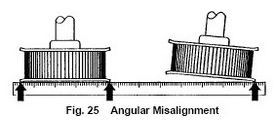
A simple procedure to check misalignment (both parallel and angular) is by using a straightedge (ruler) to check alignment as the previous illustration shows. The straightedge should be long enough to span the distance between the two outside edges of the timing belt pulley faces. Lay the ruler across the face of the two timing belt pulleys, if the two timing belt pulley faces are not even with the straightedge than you have parallel misalignment. Another possibility with using the straightedge method would be that one of the timing belt pulley faces would lay flush with the straightedge while the other timing belt pulley would have only one edge of the timing belt pulley face touching the straightedge. In this scenario an angular misalignment would be represented. This process should then be reversed using the opposite timing belt pulley as a starting point so that the total effect of the misalignment is taken into account. Remember to account for differences in the timing belt pulley edge thickness dimension and also the degree of bend on the timing belt pulley flanges.
Another procedure for checking for parallel misalignment would be to accurately measure the distance between the shafts at three (3) points along the shaft. The distance between the shafts should be the same at all three (3) points.
ALSO MAKE SURE THAT THE SHAFTS ARE RIGIDLY MOUNTED. SHAFTS SHOULD NOT DEFLECT WHEN THE TIMING BELT IS TENSIONED. A NON-RIGID MOUNT CAUSES VARIATION IN THE CENTER TO CENTER DISTANCES RESULTING IN TIMING BELT SLACK. THIS TIMING BELT SLACK COULD LEAD TO A RATCHETING OF TEETH ON THE TIMING BELT PULLEY - ESPECIALLY UNDER STARTING LOAD WITH SHAFT MISALIGNMENT.