Glossary of Terms
A | B | C | D | E | F | G | H | I | J | K | L | M | N | O | P | Q | R | S | T | U | V | W | X | Y | Z
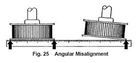
- Angular misalignment is where the driver and driven shafts are not parallel. Resulting in uneven loading of the timing belt tensile cords. The tensile cords on the high tension side are often overloaded which may cause edge cord failure which would be transmitted across the width of the timing belt. This misalignment also results in high timing belt tracking forces which causes excessive timing belt edge wear.
Aramid - Timing Belt Tensile Cord
-
Aramid fibers (most commonly known as 'Kevlar' or 'Twaron') are used to make tensile cords for timing belts. Aramid tensile cords for timing belts offer the following properties
- Low density
- High tensile modulus
- High tensile strength
- Good vibration damping
- High energy absorption
- High impact resistance
- Low material fatigue
- Good temperature resistance
- Good chemical resistance
- Low thermal conductivity
- Low compression strength
- Moderate adhesive properties
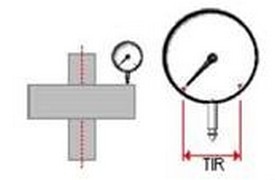
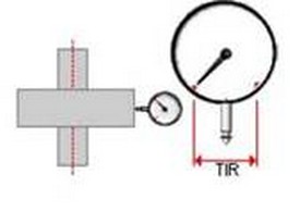
Axial Run-Out
- The total deviation of the axial reference surface noted during one revolution of the work piece. It is expressed as TIR (Total Indicator Reading).
Backlash (Timing Belt)
- Backlash can be defined as free play between two mating parts. A prime example of backlash is sloppy steering in a car, where the steering wheel can be turned left or right a small amount with no change in the direction of the car. Backlash in timing belts results from clearance between timing belt teeth and timing belt pulley grooves. This clearance is needed to allow the timing belt teeth to enter and exit the grooves smoothly with a minimum of interference; the amount of clearance necessary depends upon the timing belt tooth profile. Too much clearance creates positional inaccuracy, while too little can generate excessive noise, vibration and wear.
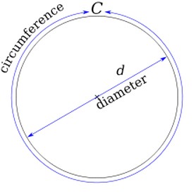
Circumference
- One of the most common basic geometric figures used when designing a power transmission component (pulley, sprocket, gear, etc) is the circle. The circle is the geometrical shape on which the entire power transmission process is based. In simple terms circumference is defined as the distance around the edge of a circle. An effortless method of obtaining this dimension is by measuring the exact length of string needed to go around the circle.
- To calculate a circle’s circumference, we must know that the ratio between the circumference and the diameter is a constant. This constant is named Pi (Π). Its value is 3.14159……..
- Calculating the circumference of a circle with a diameter of 1.27” you would get 4” (3.141159 x 1.27” = 4”). Again thinking of it as a piece of string needed to go around the outside edge of a circle that string would be 4” laid end to end.
Clearance Values
- The clearance between the timing belt teeth and the matching timing belt pulley teeth is the principal indication of backlash in a drive. Proper clearance between a timing belt tooth and a timing belt pulley groove lets the timing belt tooth enter and exit smoothly.
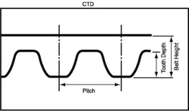
CTD - Timing Belt Tooth Profile
- CTD: (Conti Torque Drive) is the symbiosis of the HTD and the STD timing belt tooth profile and combines both profile advantages in a single timing belt tooth profile. The arch-shaped pulley-entry geometry, on the one hand, and the higher tooth, on the other, makes for ideal conditions for use on dynamic drives with simultaneously high tension load.
Elongation
- Elongation of a timing belt or stretch occurs naturally when a timing belt is placed under tension. The total tension exerted within a timing belt results from installation, as well as working loads. The amount of timing belt elongation is a function of the timing belt tensile modulus, which is influenced by the type of tensile cord and the timing belt construction.
- A timing belt with a high tensile modulus stretches less and improves positional accuracy, however in order to maintain the timing belts life the tensile cord must also exhibit flexibility.
Fiberglass - Timing Belt Tensile Cord
- Fiberglass tensile cords are the most common reinforcement in timing belts.
- Fiberglass tensile cords offer the following properties:
- Low tensile modulus
- High bending flexibility
Flanges
- Timing belts typically track to one side of a timing belt pulley during operation, and would slide off the timing belt pulley if it was not flanged.
- Flanging Guidelines:
- Two Timing Belt Pulley Drives – On simple two timing belt pulley drives, either one pulley should be flanged on both sides, or each pulley should be flanged on opposite sides.
- Multi Timing Belt Pulley Drives – On multiple timing belt pulley drives (i.e. more than two pulleys, serpentine), either every other pulley should be flanged on both sides, or every pulley should be flanged on alternating sides around the system.
- Vertical Shaft Drives – On vertical shaft drives, at least one timing belt pulley should be flanged on both sides, and the remaining timing belt pulleys should be flanged on at least the bottom side.
- Long Span Drives – Timing belts on drives with long spans, typically (8x) times the diameter of the smaller timing belt pulley require both timing belt pulleys to be flanged.
Flank (Timing Belt Pulley Tooth Flank)
- The surface area of a timing belt pulley tooth between the pitch circle and the bottom land along the length of the tooth, including the fillet.
Gear Ratios
- Understanding the concept of a gear ratio is easy if you understand the concept of the circumference of a circle. Keep in mind that the circumference of a circle is equal to the diameter of the circle multiplied by Pi (Pi is equal to 3.14159...). Therefore, if you have a circle or a gear with a diameter of 1” inch, the circumference of that circle is 3.14159” inches.
- Expanding on the concept of circumference, let’s say you have a circle whose diameter is 1.27”. The circumference of this circle would be 4” inches (3.141159 x 1.27” = 4”). Let's say that you have another circle whose diameter is 0.635” inches (1.27” inches / 2 = .0635”) with a circumference of 2” inches (3.141159 x .635” = 2”). You'll find that, because its diameter is half of the 1.27” inch circles, it has to complete two full rotations to cover the same 4” inch circumference. This explains why two gears, one half as big as the other, have a gear ratio of 2:1. The smaller gear has to rotate twice to cover the same distance covered when the larger gear rotates once.
- This leads us into talking about ratios in terms of gears (gear ratios). Gear teeth are proportional to the circumference of the gear wheel (the bigger the wheel the more teeth it has). Gear ratios can also be expressed as the relationship between the circumferences of both wheels (where d is the diameter of the smaller input gear (driver) and D is the diameter of the larger output gear (driven)).
- Counting the teeth calculates the exact gear ratio, regardless of any variations in the diameter measurement. As long as the gear teeth remain meshed, the counting of teeth and revolutions will remain perfect.
- Pitch diameter measurements are useful for determining approximate gear ratios for non-gear linkages such as V-Belt pulleys and belts. Smooth belts can slip, so even if exact pulley diameters are known, the gear ratio may vary in operation, and may even depend on the load.
- Note: V-Belt pulley ratios are calculated by dividing the pitch diameters
- Timing belt pulleys coupled with timing belts have teeth that behave just like meshing gear teeth and exact counting of teeth and revolutions can be applied with these machines. Chain sprockets coupled with chains work exactly the same way.
- In order to calculate gear ratios you just count the number of teeth in the two gears and divide.
- Note: Typically you are dividing the larger driven (D) output gear (D) (larger # of teeth) divided by the smaller driver (d) input gear (smaller # of teeth).
- So if the driven gear has 60 teeth and the driver gear has 20 teeth, the gear ratio when these two gears are connected together is 3:1 (60 teeth / 20 teeth = 3) a mechanical advantage.
- Ratios, whether by gears, timing belt pulleys and belts, chain and sprockets or anything else, are usually thought of as speed reducers, or less often, as speed increasers. They should be thought of more in terms of what they do to torque. A speed reducer is a torque increaser and vice versa. The laws of physics dictate that a change of speed via a ratio, proportionally changes the torque, as a factor of the ratio. Disregarding the friction in the system, the torque is multiplied or divided as a factor of the ratio.
- Thus a 3:1 speed reduction ratio, multiplies the input torque three (3) times (a MECHANICAL ADVANTAGE) and 1:3 speed increasing ratio would reduce the torque three (3) times (a MECHANICAL DISADVANTAGE)
- Note: Ratios cannot be added or subtracted; only multiplied or divided.
- The golden rule of gear ratios are they are the SAME no matter how you arrive at them. For example if you have a 50 tooth 8mm pitch timing belt pulley and a 25 tooth 8mm pitch timing belt pulley the ratio is 2:1 (50 tooth / 25 tooth = 2) and if you have a 100 tooth 8mm pitch timing belt pulley and a 50 tooth 8mm pitch timing belt pulley the ratio is 2:1 (100 tooth / 50 tooth = 2). These ratios are the same, clear and simple, “old math” or “new math” slide rule or calculator, it is still 2 to 1 (2:1).
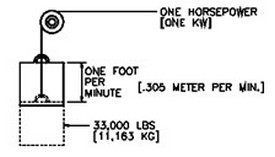
- Horsepower (HP):
- Quantity one (1) HP is the rate of work required to raise 33,000 pounds one (1) foot in one (1) minute
- Kilowatt (KW):
- Quantity one (1) KW is the rate of work required to raise 11,163 kilograms 0.305 meter in one (1) minute
- Formulas
- HP = (Force x FPM) / 33,000
- HP = (Torque in pound-inches x RPM) / 63,025
- HP = (Torque in pound-feet x RPM) / 5,252
- KW = (Nm x RPM) / 9,550
- Note: It is important to realize that when you increase or decrease speed (RPM), horsepower also increases or decreases proportionately. HOWEVER, torque always remains constant.
- Conversions:
- HP = KW x 1.341
- KW = HP x 0.7457
- ft-lb = Nm x 0.737562
- in-lb = Nm x 8.85
- Nm = ft-lb x 1.356
- Nm = in-lb x 0.113
- ft-lb/sec = HP x 550
Horsepower / RPM / Torque Relationship
| Horsepower (HP) | Speed (RPM) | Torque (T) |
| Constant ↔ | Increases ↑ | Decreases ↓ |
| Constant ↔ | Decreases ↓ | Increases ↑ |
| Increases ↑ | Constant ↔ | Increases ↑ |
| Decreases ↓ | Constant ↔ | Decreases ↓ |
| Increases ↑ | Increases ↑ | Constant ↔ |
| Decreases ↓ | Decreases ↓ | Constant ↔ |
- It is important to realize that when you increase or decrease speed (RPM), horsepower also increases or decreases proportionately. HOWEVER, torque always remains constant
- Ratios, whether by gears, belts, chain and sprockets or anything else, are usually thought of as speed reducers, or less often, as speed increasers. They should be thought of more in terms of what they do to torque. A speed reducer is a torque increaser and vice versa. The laws of physics dictate that a change of speed via a ratio, proportionally changes the torque, as a factor of the ratio. Disregarding the friction in the system, the torque is multiplied or divided as a factor of the ratio. Thus a 5:1 speed reduction ratio, multiplies the input torque five (5) times (a MECHANICAL ADVANTAGE) and 1:5 speed increasing ratio would reduce the torque 5 times (a MECHANICAL DISADVANTAGE)
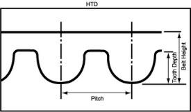
HTD - Timing Belt Tooth Profile
- (HTD: High Torque Drive) offers especially good protection from timing belt ratcheting. This is thanks to the height of its teeth and their semi-rounded geometry. However, because of the larger timing belt teeth which require substantial clearance (generating backlash) to enter and exit the pulley groove cleanly. The HTD profile is typically used on applications that require minimal positional accuracy. The HTD profile or curvilinear profile is admirably suited to transmitting high torque.
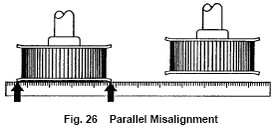
Parallel Misalignment
- Parallel misalignment is where the driver and driven shafts are parallel but the driver and driven timing belt pulleys on these shafts lie in different planes.
Pitch (Timing Belt Pitch)
- Timing belt pitch is the distance in millimeters and/or inches between two adjacent tooth centers as measured on the pitch line of the timing belt.
Pitch (Timing Belt Pulley Pitch)
- Timing belt pitch is the distance in millimeters between two adjacent tooth centers as measured on the pitch line of the timing belt.
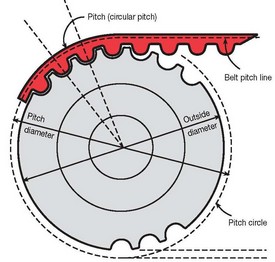
Pitch Circle (Timing Belt Pulley Pitch Circle)
- Timing belt pulley pitch circle coincides with the timing belt pitch line mating with it.
Back To Top
Pitch Diameter (Timing Belt Pulley Pitch Diameter)
- Timing belt pulley pitch diameter is always greater than its outside diameter.
Pitch Length (Timing Belt Pitch Length)
- Timing belt pitch length is the total length (circumference) in millimeters as measured along the pitch line.
Pitch Line (Timing Belt Pitch Line)
- Timing belt pitch line in theory lies within the tensile member of the timing belt
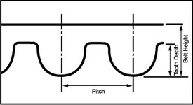
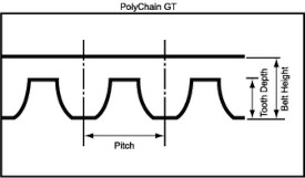
PolyChain GT - Timing Belt Tooth Profile
- The PolyChain GT timing belt tooth profile is a modified curvilinear profile that improves upon the HTD profile. Unlike the HTD timing belt profile the PolyChain GT timing belt profile features reduced tooth depth, increased flank angle, and minimized clearance. Translating into excellent ratcheting resistance and increased load carrying capacity.
Radial Run-Out
- The total variation in a direction perpendicular to the axis of rotation of an indicated surface from a plane surface of revolution. It is expressed as TIR (Total Indicator Reading).
Ratcheting (Tooth Jumping)
- Ratcheting in a timing belt drive occurs when the drive is under-tensioned. The timing belt pitch begins to mismatch the driven pulley pitch. Modified curvilinear timing belt tooth profiles (deeper and steeper teeth) have better anti-ratcheting characteristics compared to trapezoidal timing belt tooth profiles. Combining the modified curvilinear profile with a polyurethane construction increase the resistance of tooth deflection, thus providing greater anti-ratcheting characteristics than rubber timing belts.
Registration (Positioning)
- Registration is the difference in angular position between two timing belt pulleys and can be classified as STATIC or DYNAMIC. The three factors contributing to registration/positioning errors are:
- Timing Belt Elongation
- Backlash
- Timing Belt Tooth Deflection
- STATIC: Registration is defined as the movement from an initial static position to a secondary static position. In designing a system it is only critical for how accurately and consistently the movement stops at its secondary position. Potential registration errors occurring during movement is of no concern. The only concern is backlash, and the effects of timing belt elongation and timing belt tooth deflection will not influence the final outcome.
- DYNAMIC: Registration is defined as the movement required to perform a registering function while in motion with torque loads varying as the system operates. In designing a system it is critical that the rotational position of the drive pulleys in relation to each other is known at every point in time. In a system experiencing dynamic registration, all three factors (timing belt elongation, backlash and timing belt tooth deflection) will contribute to registration errors.
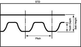
STD - Timing Belt Tooth Profile
- (STD: Super Torque Drive) provides optimum engagement performance thanks to its arched geometry. Even at high belt speeds, drives with the STD timing belt tooth profile exhibit very good running precision and are extremely quiet in operation.
Synchronous Timing Belt
- Synchronous timing belt drives operate by positively engaging the teeth molded to the timing belt with the corresponding teeth of a pulley. Synchronous timing belts do not rely on friction to transmit power (i.e. V-belts), and should not be confused with mold-notch V-belts which transmit power by the wedging action of the V-shape. The positive engagement of the two sets of meshing teeth allows synchronous timing belts to transmit large torques and withstand large accelerations. Because of the positive engagement there is little relative motion and most importantly NO SLIP between the meshing teeth. Synchronous timing belts are extremely useful in applications where indexing, positioning or a constant speed ratio is required.
Taper Bushing
- Taper Bushing (Flanged Bushing, Flangeless Bushing and Keyless Bushing)
- Tapered bushings work on a wedging action that when the tapered bushing is tightened by screws the I.D. taper of the pulley and the matching O.D. taper of the bushing are drawn together which at the same time contracts the inside diameter securing it to the shaft. The I.D. contraction is the equivalent to a press fit (interference fit) that offers a higher strength alternative for transmitting torque and resisting slippage than single or even multiple setscrew style connections. Another advantage is that it eases maintenance for installation and removal and will not mar shafts as set screws would. The three main types of tapered bushings are:
- Flanged Bushing
- Flangeless Bushing
- Keyless Bushings (Shaft Locking Devices)
- Tapered bushings work on a wedging action that when the tapered bushing is tightened by screws the I.D. taper of the pulley and the matching O.D. taper of the bushing are drawn together which at the same time contracts the inside diameter securing it to the shaft. The I.D. contraction is the equivalent to a press fit (interference fit) that offers a higher strength alternative for transmitting torque and resisting slippage than single or even multiple setscrew style connections. Another advantage is that it eases maintenance for installation and removal and will not mar shafts as set screws would. The three main types of tapered bushings are:
- Flanged Bushing
- The two most popular types of flanged bushings:
- Flanged Bushing - Split Taper
- Flanged Bushing - QD
- The two most popular types of flanged bushings:
- Flanged Bushing – Split Taper
- The tapered portion of the split tapered bushing is split in two places, with the split ending before it enters the flange. The bushing is keyed to the shaft, and the outside diameter of the barrel is keyed to the pulley component as well.
- Advantages:
- The double keyed connection allows the drive to continue to operate (transmit torque) even if the fasteners connection the mating tapers comes loose.
- Disadvantages:
- The “flange” on the pulley increases weight and requires more space for mounting. The split taper bushing fasteners can only be inserted from the flange side only.
- Flanged Bushing - QD
- The tapered portion of a QD bushing is split in one place only, with the split extending through the flange. There is also only one keyed connection between the bushing and shaft.
- Advantages:
- The QD bushing can be inserted from either direction for standard or reverse mounting.
- Disadvantages:
- The “flange” on the pulley increases weight and requires more space for mounting.
- Since the only keyed connection is between the bushing and the shaft. If the fasteners securing the bushing to the pulley become loose the bushing could slip within the pulley.
- Flangeless Bushing
- Are typically called TAPER LOCK bushings and are differentiated by not having a flange.
- Advantages:
- Larger taper angle permits tightening the pulley with less displacement along the shaft. This makes it easier to accurately locate the pulley on the shaft where precise positioning is required.
- Full length of the bushing supports the pulley.
- The flangeless design allows for use of less shaft space.
- Disadvantages:
- Difficult installation, requiring the installation instructions be fully read and followed.
- Keyless Bushing
- Keyless bushings convert clamping action between inner and outer tapered rings into circumferential uniform radial pressure that locks the device to the shaft and the pulley. As the name implies keyless bushings do not have a keyway.
- Advantages:
- Use of smaller diameter shaft sizes or hollow shaft sizes for weight reduction.
- Allows for infinite adjustment for timing purposes.
- Can be used over damaged shaft keyways.
- Ability to transmit high torques.
- Ability to take high axial forces and shocks.
- Disadvantages:
- Cost is substantially more than other taper bushings.
- Limited number of bore sizes.
Tensile Member
- The tensile cord provides the backbone of the timing belt. These cords give the timing belt high strength, excellent flex life and high resistance to elongation. Commonly used materials include fiberglass, aramid (kevlar), steel, polyester and carbon fiber. Tensile cord members are constructed of several filaments twisted around each other. The twisting of the filaments into a cord is commonly referred to as “S” twist or a “Z” twist. The two different twists will cause the timing belt to track to one side of the timing belt pulley depending on which twist is employed. To counteract this force a timing belt is typically constructed with the use of both twists wound in opposite directions around the timing belt. However, with that said the timing belt still has the tendency to favor the tracking of the “S” twist.
Tooth Deflection (Tooth Deformation)
- No matter which timing belt tooth profile is chosen if it deforms or deflects under a torque load, it causes lost motion which increases positional inaccuracy. The main factors contributing to timing belt tooth deflection include torque loading, timing belt pulley size, installation tension and timing belt material type. As can be imagined the harder the timing belt material type the less the deflection. However, using to hard of a material negatively impacts the belt’s flex fatigue characteristics and increases drive noise.
- The twisting or turning effort around a shaft tending to cause rotation. Torque is determined by multiplying the applied force by the distance from the point where force is applied to the shaft center. It is measured in terms of pounds, or ounces; acting on a lever arm, measured in terms of feet or inches (Metric = Newton Meters (Nm). This lever arm is connected to a shaft that can rotate.
- Torque (ft-lb) = Force x Distance
- Note: Torque can be present at zero (0) rpm, in which case the horsepower would be zero (0).
- Full-Load Torque: Full-load torque is the torque to produce the rated power at full speed of the motor.
- Formulas
- Torque (in-lb) = (63,025 x HP) / RPM
- Torque (ft-lb) = (5,252 x HP) / RPM
- Torque (in-lb) = (9,550 x KW) / RPM
- Note: Ratios, whether by gears, belts, chain and sprockets or anything else, are usually thought of as speed reducers, or less often, as speed increasers. They should be thought of more in terms of what they do to torque. A speed reducer is a torque increaser and vice versa. The laws of physics dictate that a change of speed via a ratio, proportionally changes the torque, as a factor of the ratio. Disregarding the friction in the system, the torque is multiplied or divided as a factor of the ratio. Thus a 5:1 speed reduction ratio, multiplies the input torque five (5) times (a MECHANICAL ADVANTAGE) and 1:5 speed increasing ratio would reduce the torque 5 times (a MECHANICAL DISADVANTAGE)
- Conversions
- HP = KW x 1.341
- KW = HP x 0.7457
- ft-lb = Nm x 0.737562
- in-lb = Nm x 8.85
- Nm = ft-lb x 1.356
- Nm = in-lb x 0.113
- ft-lb/sec = HP x 550
Trapezoidal - Timing Belt Tooth Profile
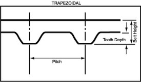
Trapezoidal timing belt tooth profiles provide a high degree of precision indexing or registration. Unlike curvilinear timing belt profile belts which have full flank contact, trapezoidal timing belts contact the pulley in the root radius (radius of the root circle which contains the bottom of the tooth spaces) and in the upper flank area only. The load carrying capacities of the trapezoidal tooth profile is severely limited and makes the timing belt highly susceptible to ratcheting (tooth jumping).
Back To Top